MetaPost 中的各种技巧 (2019)
MetaPost 中的各种技巧
阅读时间:8 分钟 浏览量:1.4 万 LaTeX 翻译 原文作者: Sergey Slyusarev
绘制矢量图片的最佳工具是什么? 对我来说,可能对许多人来说,答案很明显:Illustrator,或者,也许是 Inkscape。 至少当有人要求我为物理教科书绘制大约八百张图表时,我是这么认为的。 没什么特别的,只是一堆带有球体、弹簧、滑轮、透镜等的黑白插图。 那时,这本书已经确定要用 LaTeX 制作了,我拿到了一些嵌入图像的 MS Word 文档。 其中一些是扫描自其他书籍的图片,另一些是铅笔画。 想象着日日夜夜用 Inkscape 处理这些东西让我感到头晕,所以我很快就幻想了一种更自动化的解决方案。 不知何故,MetaPost 成了这些幻想的焦点。
 使用 MetaPost(或类似方案)的主要优点是,每张图片都可以是几个变量的函数。 这种图片可以根据布局的任何不可预见的情况进行快速调整,而不会破坏插图的重要内部关系(这是我真正关心的事情),这在使用更传统的工具时不容易实现。 此外,重复出现的元素,所有这些球体和弹簧,都可以比传统工具在相同的时间限制下更具视觉吸引力。 我想制作一些带有阴影线的图片,类似于你在旧书中遇到的那些。
 首先,我需要能够生成一些粗细不同的曲线。 这里的主要复杂性在于构建一条以不同距离跟随原始曲线的曲线。 我使用了可能最原始的方法,该方法归结为简单地将连接 Bezier 曲线控制点的线段移动给定的距离,只是这个距离沿曲线变化。
 在大多数情况下,它的工作正常。
示例代码
从这里开始,假设该库已下载 并且 input fiziko.mp; 存在于 MetaPost 代码中。 最快的方法是使用 ConTeXt(那么你不需要 beginfig 和 endfig):
\starttext
\startMPcode
input fiziko.mp;
% the code goes here
\stopMPcode
\stoptext
或 LuaLaTeX:
\documentclass{article}
\usepackage{luamplib}
\begin{document}
\begin{mplibcode}
input fiziko.mp;
% the code goes here
\end{mplibcode}
\end{document}
beginfig(3);
path p, q;
% MetaPost's syntax is reasonably readable, so I'll comment mostly on my stuff
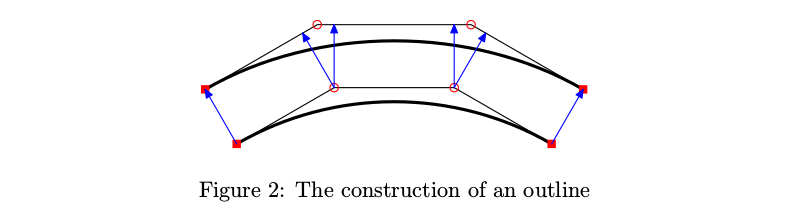
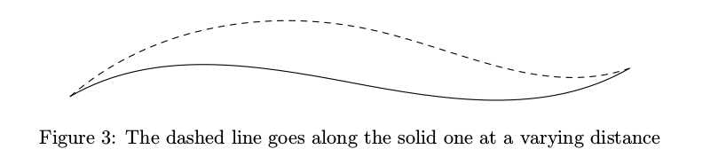
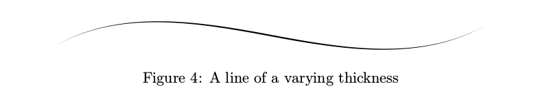
p := (0,-1/4cm){dir(30)}..(5cm, 0)..{dir(30)}(10cm, 1/4cm);
q := offsetPath(p)(1cm*sin(offsetPathLength*pi));
% first argument is the path itself, second is a function of the position along this path (offsetPathLength changes from 0 to 1), which determines how far the outline is from the original line
draw p;
draw q dashed evenly;
endfig;
两个轮廓可以组合在一起,形成可变粗细笔画的轮廓线。
示例代码
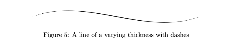
beginfig(4);
path p, q[];
p := (0,-1/4cm){dir(30)}..(5cm, 0)..{dir(30)}(10cm, 1/4cm);
q1 := offsetPath(p)(1/2pt*(sin(offsetPathLength*pi)**2));
% outline on one side
q2 := offsetPath(p)(-1/2pt*(sin(offsetPathLength*pi)**2));
% and on the other
fill q1--reverse(q2)--cycle;
endfig;
线条粗细应具有一些下限,否则,某些线条会太细而无法正确打印,并且看起来不太好。 一种选择(我选择的一种)是使太细的线条变成虚线,以便每单位长度的总墨水量与预期的细线大致相同。 换句话说,该算法不是减少线条侧面的墨水量,而是从线条本身中提取一些墨水。
示例代码
beginfig(5);
path p;
p := (0,-1/4cm){dir(30)}..(5cm, 0)..{dir(30)}(10cm, 1/4cm);
draw brush(p)(1pt*(sin(offsetPathLength*pi)**2));
% the arguments are the same as for the outline
endfig;
一旦有了可工作的可变粗细线条,就可以绘制球体了。 球体可以被描绘成一系列同心圆,其线条粗细根据计算球体上特定点的亮度的函数的输出而变化。

示例代码
beginfig(6);
draw sphere.c(1.2cm);
draw sphere.c(2.4cm) shifted (2cm, 0);
endfig;
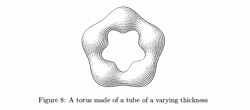
另一个方便的构建块是“管子”。 粗略地说,它是一个可以弯曲的圆柱体。 只要直径是恒定的,它就很简单。
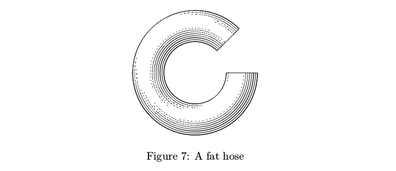
示例代码
beginfig(7);
path p;
p := subpath (1,8) of fullcircle scaled 3cm;
draw tube.l(p)(1/2cm);
% arguments are the path itself and the tube radius
endfig;
如果直径不是恒定的,事情会变得更加复杂:笔画的数量应根据管子的粗细而变化,以便在考虑光线之前,每单位面积的墨水量保持恒定。
示例代码
beginfig(8);
path p;
p := pathSubdivide(fullcircle, 2) scaled 3cm;
% this thing splits every segment between the points of a path (here—fullcircle) into several parts (here—2)
draw tube.l(p)(1/2cm + 1/6cm*sin(offsetPathLength*10pi));
endfig;
还有带有横向阴影线的管子。 在这种情况下,保持墨水量恒定的问题变得更加棘手,因此通常这些管子看起来有点蓬乱。
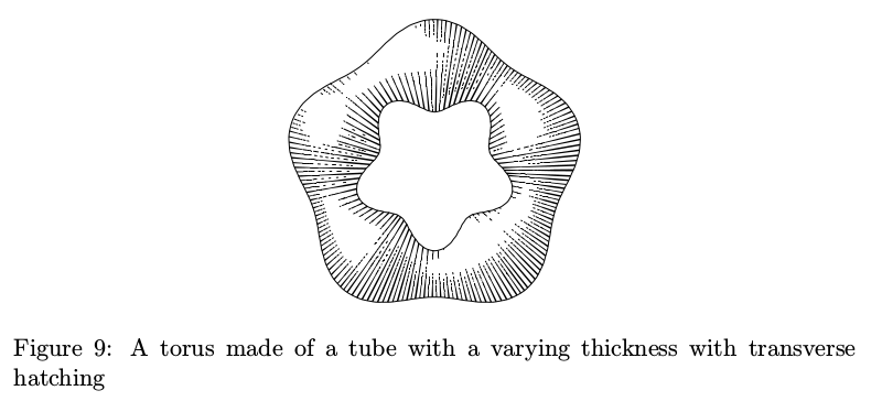
示例代码
beginfig(9);
path p;
p := pathSubdivide(fullcircle, 2) scaled 3cm;
draw tube.t(p)(1/2cm + 1/6cm*sin(offsetPathLength*10pi));
endfig;
管子可用于构建各种对象:从圆锥体和圆柱体到栏杆。

示例代码
beginfig(10);
draw tube.l ((0, 0) -- (0, 3cm))((1-offsetPathLength)*1cm) shifted (-3cm, 0);
% a very simple cone
path p;
p := (-1/2cm, 0) {dir(175)} .. {dir(5)} (-1/2cm, 1/8cm) {dir(120)} .. (-2/5cm, 1/3cm) .. (-1/2cm, 3/4cm) {dir(90)} .. {dir(90)}(-1/4cm, 9/4cm){dir(175)} .. {dir(5)}(-1/4cm, 9/4cm + 1/5cm){dir(90)} .. (-2/5cm, 3cm);
% baluster's envelope
p := pathSubdivide(p, 6);
draw p -- reverse(p xscaled -1) -- cycle;
tubeGenerateAlt(p, p xscaled -1, p rotated -90);
% a more low-level stuff than tube.t, first two arguments are tube's sides and the third is the envelope. The envelope is basically a flattened out version of the outline, with line length along the x axis and the distance to line at the y. In the case of this baluster, it's simply its side rotated 90 degrees.
endfig;
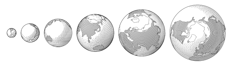
库中包含一些可以从这些原语构建的结构。 例如,地球基本上是一个球体。

示例代码
beginfig(11);
draw globe(1cm, -15, 0) shifted (-6/2cm, 0);
% radius, west longitude, north latitude, both decimal
draw globe(3/2cm, -30.280577, 59.939461);
draw globe(4/3cm, -140, -30) shifted (10/3cm, 0);
endfig;
然而,这里的阴影线是纬向的,并且控制线条密度比具有“同心”阴影线的常规球体困难得多,因此它是一种不同的球体。
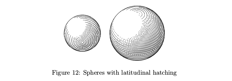
示例代码
beginfig(12);
draw sphere.l(2cm, -60);
% diameter and latitude
draw sphere.l(3cm, 45) shifted (3cm, 0);
endfig;
重量是由两种类型的管子制成的简单结构。

示例代码
beginfig(13);
draw weight.s(1cm);
% weight height
draw weight.s(2cm) shifted (2cm, 0);
endfig;
还有一个工具可以将管子打结。
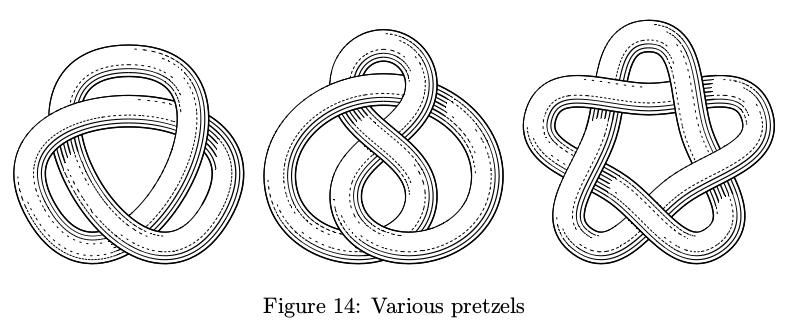
示例代码。 为了简洁起见,仅一个结。
beginfig(14);
path p;
p := (dir(90)*4/3cm) {dir(0)} .. tension 3/2 ..(dir(90 + 120)*4/3cm){dir(90 + 30)} .. tension 3/2 ..(dir(90 - 120)*4/3cm){dir(-90 - 30)} .. tension 3/2 .. cycle;
p := p scaled 6/5;
addStrandToKnot (primeOne) (p, 1/4cm, "l", "1, -1, 1");
% first, we add a strand of width 1/4cm going along the path p to the knot named primeOne. its intersections along the path go to layers "1, -1, 1" and the type of tube is going to be "l".
draw knotFromStrands (primeOne);
% then the knot is drawn. you can add more than one strand.
endfig;
结中的管子像它们应该的那样在彼此上投下阴影。 理论上,此功能可以在其他上下文中使用,但是由于我没有深入研究第三维的计划,因此用户界面有些不足,并且阴影仅对某些对象有效。
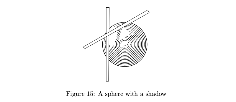
示例代码
beginfig(15);
path shadowPath[];
boolean shadowsEnabled;
numeric numberOfShadows;
shadowsEnabled := true;
% shadows need to be turned on
numberOfShadows := 1;
% number of shadows should be specified
shadowPath0 := (-1cm, -2cm) -- (-1cm, 2cm) -- (-1cm +1/6cm, 2cm) -- (-1cm + 1/8cm, -2cm) -- cycle;
% shadow-dropping object should be a closed path
shadowDepth0 := 4/3cm;
% it's just this high above the object on which the shadow falls
shadowPath1 := shadowPath0 rotated -60;
shadowDepth1 := 4/3cm;
draw sphere.c(2.4cm);
% shadows work ok only with sphere.c and tube.l with constant diameter
fill shadowPath0 withcolor white;
draw shadowPath0;
fill shadowPath1 withcolor white;
draw shadowPath1;
endfig;
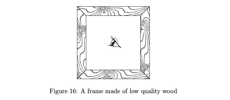
当然,您需要一个木纹纹理(更新:自从发布此文章的俄语版本以来,据我所知,该库首次在实际项目中使用已经发生,并且木纹纹理派上了用场,所以这最终并不是一个玩笑)。 树枝及其生长如何影响年轮的图案是一个值得认真研究的主题。 我能想到的最简单的工作模型如下:年轮是平行的平面,被生长的树枝扭曲; 因此,表面被不同位置的一系列不太复杂的“树枝函数”修改,并且表面的等值线被视为年轮图案。
示例代码
beginfig(16);
numeric w, b;
pair A, B, C, D, A', B', C', D';
w := 4cm;
b := 1/2cm;
A := (0, 0);
A' := (b, b);
B := (0, w);
B' := (b, w-b);
C := (w, w);
C' := (w-b, w-b);
D := (w, 0);
D' := (w-b, b);
draw woodenThing(A--A'--B'--B--cycle, 0);
% a piece of wood inside the A--A'--B'--B--cycle path, with wood grain at 0 degrees
draw woodenThing(B--B'--C'--C--cycle, 90);
draw woodenThing(C--C'--D'--D--cycle, 0);
draw woodenThing(A--A'--D'--D--cycle, 90);
eyescale := 2/3cm;
% scale for the eye
draw eye(150) shifted 1/2[A,C];
% the eye looks in 150 degree direction
endfig;
上图中的眼睛睁大或稍微眯起,并且它的瞳孔也会改变大小。 它可能没有任何实际意义,但机械上相似的眼睛看起来很无聊。

示例代码
beginfig(17);
eyescale := 2/3cm;
% 1/2cm by default
draw eye(0) shifted (0cm, 0);
draw eye(0) shifted (1cm, 0);
draw eye(0) shifted (2cm, 0);
draw eye(0) shifted (3cm, 0);
draw eye(0) shifted (4cm, 0);
endfig;
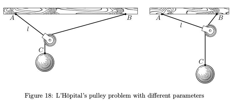
大多数时候,这些插图并没有那么复杂,但是更严格的方法将需要解决教科书中的许多问题才能正确地说明它们。 比如说,L'Hôpital 的滑轮问题(它不在那本教科书中,但无论如何):在长度为  的绳索上,悬挂在点
  处,悬挂着一个滑轮;它钩在另一根绳索上,悬挂在点
  处,其末端带有重量
  。 问题是:如果滑轮和绳索的重量都为零,则重量会落到哪里? 令人惊讶的是,此问题的解决方案和构造并不那么简单。 但是,通过使用几个变量,您可以使图片看起来适合页面,同时保持准确性。
示例代码
vardef lHopitalPulley (expr AB, l, m) =
% distance AB between the suspension points of the ropes and their lengths l and m. “Why no units of length?”, you may ask. It's because some calculations inside can cause arithmetic overflow in MetaPost.
save A, B, C, D, E, o, a, x, y, d, w, h, support;
image(
pair A, B, C, D, E, o[];
path support;
numeric a, x[], y[], d[], w, h;
x1 := (l**2 + abs(l)*((sqrt(8)*AB)++l))/4AB;
% the solution
y1 := l+-+x1;
% second coordinate is trivial
y2 := m - ((AB-x1)++y1);
% as well as the weight's position
A := (0, 0);
B := (AB*cm, 0);
D := (x1*cm, -y1*cm);
C := D shifted (0, -y2*cm);
d1 := 2/3cm; d2 := 1cm; d3 := 5/6d1;
% diameters of the pulley, weight and the pulley wheel
w := 2/3cm; h := 1/3cm;
% parameters of the wood block
o1 := (unitvector(C-D) rotated 90 scaled 1/2d3);
o2 := (unitvector(D-B) rotated 90 scaled 1/2d3);
E := whatever [D shifted o1, C shifted o1]
= whatever [D shifted o2, B shifted o2];
% pulley's center
a := angle(A-D);
support := A shifted (-w, 0) -- B shifted (w, 0) -- B shifted (w, h) -- A shifted (-w, h) -- cycle;
draw woodenThing(support, 0);
% wood block everything is suspended from
draw pulley (d1, a - 90) shifted E;
% the pulley
draw image(
draw A -- D -- B withpen thickpen;
draw D -- C withpen thickpen;
) maskedWith (pulleyOutline shifted E);
% ropes should be covered with the pulley
draw sphere.c(d2) shifted C shifted (0, -1/2d2);
% sphere as a weight
dotlabel.llft(btex $A$ etex, A);
dotlabel.lrt(btex $B$ etex, B);
dotlabel.ulft(btex $C$ etex, C);
label.llft(btex $l$ etex, 1/2[A, D]);
) enddef;
beginfig(18);
draw lHopitalPulley (6, 2, 11/2);
% now you can choose the right parameters
draw lHopitalPulley (3, 5/2, 3) shifted (8cm, 0);
endfig;
那教科书呢? 唉,当几乎所有插图和布局都准备就绪时,发生了一些事情,教科书被取消了。 也许是因为这个原因,我决定从头开始重写原始库的大部分功能(我选择不使用任何原始代码,尽管我间接为这些代码付了钱)并将它放在 GitHub 上。 原始库中存在的一些东西,例如用于绘制汽车和拖拉机的功能,我没有包括在内,而添加了一些新功能,例如结。 它的运行速度并不快:在我的笔记本电脑上使用 i5-4200U 1.6 GHz 的 LuaLaTeX 生成本文的所有图片大约需要一分钟。 此处和那里使用了伪随机数生成器,因此没有两张相似的图片是完全相同的(这是一个功能),并且每次运行都会产生略有不同的图片。 为了避免出现意外,您可以简单地设置 randomseed := some number 并享受每次运行的相同结果。 非常感谢 dr ord 和 Mikael Sundqvist 在英语版本方面的帮助。
标签:
Hubs: